Lexus ES: Brake Switch "A" Circuit Short to Ground (P057111)
DESCRIPTION
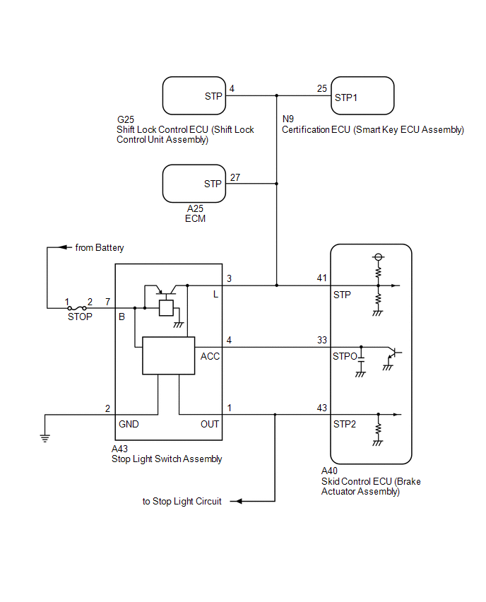
The skid control ECU (brake actuator assembly) receives stop light switch assembly signals and uses them to determine whether or not the brakes are applied.
When the brake pedal is depressed and no signal is received from the stop light switch assembly, this DTC is output.
| DTC No. | Detection Item | DTC Detection Condition | Trouble Area |
|---|---|---|---|
| P057111 | Brake Switch "A" Circuit Short to Ground | Either of the following is detected when the vehicle speed of 3 km/h (2 mph) or more:
|
|
| Vehicle Condition | |||
|---|---|---|---|
| Pattern 1 | Pattern 2 | ||
| Diagnosis Condition | The stop light switch assembly off and vehicle speed of 3 km/h (2 mph) or more. | ○ | ○ |
| Malfunction Status | The stop light switch assembly is judged to be on based on the master cylinder pressure value. | ○ | - |
| The master cylinder pressure is more than 8 MPa (81.6 kgf/cm2, 1160 psi). | - | ○ | |
| Detection Time | 3 seconds or more. | 3 seconds or more. | |
| Number of Trips | 1 trip | 1 trip | |
HINT:
DTC will be output when conditions for either of the patterns in the table above are met.
WIRING DIAGRAM
CAUTION / NOTICE / HINT
NOTICE:
- Inspect the fuses for circuits related to this system before performing the following procedure.
-
After replacing the skid control ECU (brake actuator assembly), perform acceleration sensor zero point calibration and store system information memorization.
Click here
.gif)
PROCEDURE
| 1. | READ VALUE USING TECHSTREAM (MASTER CYLINDER SENSOR) |
(a) Connect the Techstream to the DLC3.
(b) Turn the engine switch on (IG).
(c) Enter the following menus: Chassis / Brake/EPB / Data List.
Chassis > Brake/EPB > Data List| Tester Display | Measurement Item | Range | Normal Condition | Diagnostic Note |
|---|---|---|---|---|
| Master Cylinder Sensor 1 | Master cylinder pressure sensor pressure (value detected by ECU) | Min.: -1.00 MPa, Max.: 23.99 MPa | Brake pedal released: -1.00 to 0.00 MPa | Reading increases when brake pedal is depressed |
| Tester Display |
|---|
| Master Cylinder Sensor 1 |
(d) Check the value of Data List item Master Cylinder Sensor 1 when the brake pedal is released.
OK:
The value of Data List item Master Cylinder Sensor 1 when the brake pedal is released is less than 0.15 MPa.
| NG |  | GO TO STEP 4 |
|

| 2. | CHECK HARNESS AND CONNECTOR (STOP LIGHT SWITCH ASSEMBLY SIGNAL INPUT CIRCUIT) |
| (a) Make sure that there is no looseness at the locking part and the connecting part of the connector. OK: The connector is securely connected. |
|
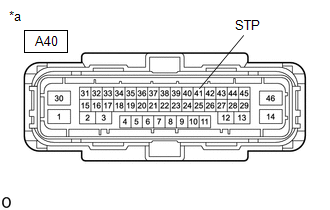
(b) Disconnect the A40 skid control ECU (brake actuator assembly) connector.
(c) Check both the connector case and the terminals for deformation and corrosion.
OK:
No deformation or corrosion.
(d) Measure the voltage according to the value(s) in the table below.
Standard Voltage:
| Tester Connection | Condition | Specified Condition |
|---|---|---|
| A40-41 (STP) - Body ground | Brake pedal depressed | 11 to 14 V |
| OK | | REPLACE BRAKE ACTUATOR ASSEMBLY |
|
| 3. | CHECK HARNESS AND CONNECTOR (STOP LIGHT SWITCH ASSEMBLY - BRAKE ACTUATOR ASSEMBLY) |
(a) Make sure that there is no looseness at the locking part and the connecting part of the connector.
OK:
The connector is securely connected.
(b) Disconnect the A40 skid control ECU (brake actuator assembly) connector.
(c) Disconnect the A43 stop light switch assembly connector.
(d) Check both the connector case and the terminals for deformation and corrosion.
OK:
No deformation or corrosion.
(e) Measure the resistance according to the value(s) in the table below.
Standard Resistance:
| Tester Connection | Condition | Specified Condition |
|---|---|---|
| A43-3 (L) - A40-41 (STP) | Always | Below 1 Ω |
| A43-3 (L) or A40-41 (STP) - Body ground and other terminals | Always | 10 kΩ or higher |
| OK | | REPLACE STOP LIGHT SWITCH ASSEMBLY |
| NG | | REPAIR OR REPLACE HARNESS OR CONNECTOR |
| 4. | CHECK DTC |
(a) Connect the Techstream to the DLC3.
(b) Turn the engine switch on (IG).
(c) Read the DTCs following the prompts on the Techstream. Enter the following menus: Chassis / Brake/EPB / Trouble Codes.
Chassis > Brake/EPB > Trouble Codes(d) Check the details of the DTCs.
| Result | Proceed to |
|---|---|
| P057111 and C05401C, C054028 and/or C054049 are output simultaneously | A |
| P057111 is output | B |
| A | | REPAIR CIRCUITS INDICATED BY OUTPUT DTCS |
| B | | GO TO BRAKE SYSTEM |
READ NEXT:
 Brake Switch "A" Circuit Short to Ground (P057111)
DESCRIPTION The skid control ECU (brake actuator assembly) receives stop light switch assembly signals and uses them to determine whether or not the brakes are applied. When the brake pedal is depress
Brake Switch "A" Circuit Short to Battery (P057112)
DESCRIPTION The skid control ECU (brake actuator assembly) receives stop light switch assembly signals and uses them to determine whether or not the brakes are applied. DTCs may be stored if either of
Brake Switch "A" Circuit Short to Battery (P057112)
DESCRIPTION The skid control ECU (brake actuator assembly) receives stop light switch assembly signals and uses them to determine whether or not the brakes are applied. DTCs may be stored if either of
SEE MORE:
Communication Error from VSC to ECM Invalid Serial Data Received (P163081)
DESCRIPTION The skid control ECU (brake booster with master cylinder assembly) sends signals such as brake request signals to the hybrid vehicle control ECU. If an abnormal signal is detected, the hybrid vehicle control ECU stores DTC P163081. DTC No. Detection Item DTC Detection Condition
Parts Location
PARTS LOCATION ILLUSTRATION *1 DEICER RELAY *2 NO. 2 ENGINE ROOM RELAY BLOCK AND NO. 2 ENGINE ROOM JUNCTION BLOCK ASSEMBLY - DEICER FUSE *3 MULTI-DISPLAY ASSEMBLY - FRONT WIPER DEICER SWITCH *4 WINDSHIELD DEICER WIRE (WINDSHIELD GLASS) *5 DLC3 *6 AIR CONDITIONING AMPLIF
