Lexus ES: Tilt Position Sensor or Tilt Motor Circuit Component Internal Failure (B261096)
DESCRIPTION
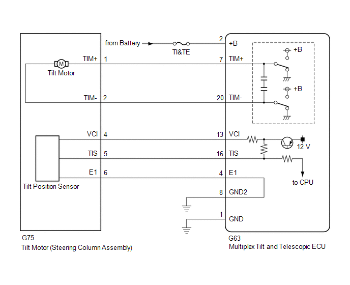
The tilt motor (steering column assembly) is operated by the power source voltage supplied from the multiplex tilt and telescopic ECU and tilts the steering column up and down. The tilt position sensor (Hall IC) in the tilt motor (steering column assembly) detects the tilt angle of the steering column assembly and sends a signal to the multiplex tilt and telescopic ECU based on that angle.
| DTC No. | Detection Item | DTC Detection Condition | Trouble Area |
|---|---|---|---|
| B261096 | Tilt Position Sensor or Tilt Motor Circuit Component Internal Failure | Tilt operation stops within the operation range while operating. |
|
WIRING DIAGRAM
CAUTION / NOTICE / HINT
NOTICE:
Inspect the fuses for circuits related to this system before performing the following procedure.
PROCEDURE
| 1. | PERFORM ACTIVE TEST USING TECHSTREAM (TILT MOTOR) |
(a) Turn the engine switch off.
(b) Connect the Techstream to the DLC3.
(c) Turn the engine switch on (IG).
(d) Turn the Techstream on.
(e) Check that the steering wheel tilts up and down.
(f) Enter the following menus: Body Electrical / Tilt & Telescopic / Active Test.
Body Electrical > Tilt&Telescopic > Active Test| Tester Display |
|---|
| Tilt Motor |
| Tester Display | Measurement Item | Control Range |
|---|---|---|
| Tilt Motor | Tilt operation | UP/DOWN |
OK:
The steering wheel tilts up and down.
| NG | .gif) | GO TO STEP 6 |
|
.gif)
| 2. | CHECK HARNESS AND CONNECTOR (MULTIPLEX TILT AND TELESCOPIC ECU - TILT POSITION SENSOR (STEERING COLUMN ASSEMBLY)) |
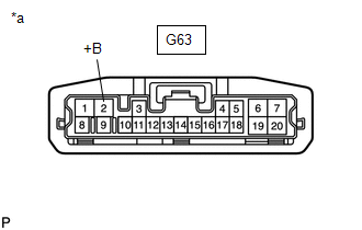
(a) Disconnect the G63 multiplex tilt and telescopic ECU connector.
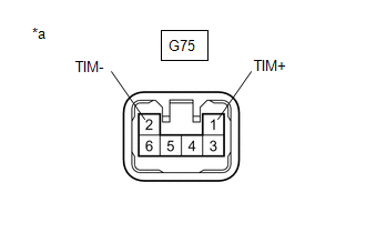
(b) Disconnect the G75 tilt motor (steering column assembly) connector.
(c) Measure the resistance according to the value(s) in the table below.
Standard Resistance:
| Tester Connection | Condition | Specified Condition |
|---|---|---|
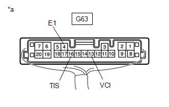
| G63-13 (VCI) - G75-4 (VCI) | Always | Below 1 Ω |
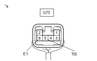
| G63-16 (TIS) - G75-5 (TIS) | Always | Below 1 Ω |
| G63-4 (E1) -G75-6 (E1) | Always | Below 1 Ω |
| G63-13 (VCI) or G75-4 (VCI) - Body ground | Always | 10 kΩ or higher |
| G63-16 (TIS) or G75-5 (TIS) - Body ground | Always | 10 kΩ or higher |
| G63-4 (E1) or G75-6 (E1) - Body ground | Always | 10 kΩ or higher |
| NG | | REPAIR OR REPLACE HARNESS OR CONNECTOR |
|
| 3. | CHECK HARNESS AND CONNECTOR (MULTIPLEX TILT AND TELESCOPIC ECU - BODY GROUND) |
| (a) Disconnect the G63 multiplex tilt and telescopic ECU connector. |
|
(b) Measure the resistance according to the value(s) in the table below.
Standard Resistance:
| Tester Connection | Condition | Specified Condition |
|---|---|---|
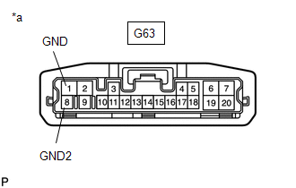
| G63-1 (GND) - Body ground | Always | Below 1 Ω |
| G63-8 (GND2) - Body ground | Always | Below 1 Ω |
| NG | | REPAIR OR REPLACE HARNESS OR CONNECTOR |
|
| 4. | CHECK MULTIPLEX TILT AND TELESCOPIC ECU (VCI, TIS TERMINAL VOLTAGE) |
| (a) Reconnect the G63 multiplex tilt and telescopic ECU connector. |
|
(b) Disconnect the G75 tilt motor (steering column assembly) connector.
(c) Measure the voltage according to the value(s) in the table below.
Standard Voltage:
| Tester Connection | Condition | Specified Condition |
|---|---|---|
| G63-13 (VCI) - G63-4 (E1) | Engine switch on (IG) | 8 to 14 V |
| G63-16 (TIS) - G63-4 (E1) | Engine switch on (IG) | 8 to 14 V |
| NG | | REPLACE MULTIPLEX TILT AND TELESCOPIC ECU |
|
| 5. | CHECK TILT POSITION SENSOR (STEERING COLUMN ASSEMBLY) |
| (a) Reconnect the G63 multiplex tilt and telescopic ECU connector. |
|
(b) Reconnect the G75 tilt motor (steering column assembly) connector.
(c) Measure the voltage according to the value(s) in the table below.
Standard Voltage:
| Tester Connection | Condition | Specified Condition |
|---|---|---|
| G75-5 (TIS) - G75-6 (E1) | Steering wheel tilting up or tilting down | Pulse generation High: 8 to 14 V Low: Below 1 V |
| OK | | REPLACE MULTIPLEX TILT AND TELESCOPIC ECU |
| NG | | REPLACE STEERING COLUMN ASSEMBLY |
.gif)
| 6. | CHECK HARNESS AND CONNECTOR (MULTIPLEX TILT AND TELESCOPIC ECU - BATTERY) |
| (a) Disconnect the G63 multiplex tilt and telescopic ECU connector. |
|
(b) Measure the voltage according to the value(s) in the table below.
Standard Voltage:
| Tester Connection | Condition | Specified Condition |
|---|---|---|
| G63-2 (+B) - Body ground | Engine switch off | 11 to 14 V |
| NG | | REPAIR OR REPLACE HARNESS OR CONNECTOR |
|
| 7. | CHECK HARNESS AND CONNECTOR (MULTIPLEX TILT AND TELESCOPIC ECU - BODY GROUND) |
| (a) Disconnect the G63 multiplex tilt and telescopic ECU connector. |
|
(b) Measure the resistance according to the value(s) in the table below.
Standard Resistance:
| Tester Connection | Condition | Specified Condition |
|---|---|---|
| G63-1 (GND) - Body ground | Always | Below 1 Ω |
| G63-8 (GND2) - Body ground | Always | Below 1 Ω |
| NG | | REPAIR OR REPLACE HARNESS OR CONNECTOR |
|
| 8. | CHECK HARNESS AND CONNECTOR (MULTIPLEX TILT AND TELESCOPIC ECU - TILT MOTOR (STEERING COLUMN ASSEMBLY)) |
(a) Disconnect the G63 multiplex tilt and telescopic ECU connector.
(b) Disconnect the G75 tilt motor (steering column assembly) connector.
(c) Measure the resistance according to the value(s) in the table below.
Standard Resistance:
| Tester Connection | Condition | Specified Condition |
|---|---|---|
| G63-7 (TIM+) - G75-1 (TIM+) | Always | Below 1 Ω |
| G63-20 (TIM-) - G75-2 (TIM-) | Always | Below 1 Ω |
| G63-7 (TIM+) or G75-1 (TIM+) - Body ground | Always | 10 kΩ or higher |
| G63-20 (TIM-) or G75-2 (TIM-) - Body ground | Always | 10 kΩ or higher |
| NG | | REPAIR OR REPLACE HARNESS OR CONNECTOR |
|
| 9. | CHECK TILT MOTOR (STEERING COLUMN ASSEMBLY) |
| (a) Disconnect the G75 tilt motor (steering column assembly) connector. |
|
(b) Apply 12 V battery voltage to the tilt motor (steering column assembly) connector. Then check the steering wheel tilt operation.
OK:
| Measurement Condition | Specified Condition |
|---|---|
| The steering wheel tilts up. |
| The steering wheel tilts down. |
| OK | | REPLACE MULTIPLEX TILT AND TELESCOPIC ECU |
| NG | | REPLACE STEERING COLUMN ASSEMBLY |
READ NEXT:
 Telescopic Position Sensor or Telescopic Motor Circuit Component Internal Failure (B261196)
DESCRIPTION The telescopic motor (steering column assembly) is operated by the power source voltage supplied from the multiplex tilt and telescopic ECU and slides the steering column assembly forward
ECU Power Source Circuit System Voltage Low (B2620A2)
DESCRIPTION The ECU power source circuit supplies positive (+) voltage to the multiplex tilt and telescopic ECU. DTC No. Detection Item DTC Detection Condition Trouble Area B2620A2 ECU
Lost Communication with Body Control Module "B" Missing Message (U014287,U015587,U020887)
DESCRIPTION The multiplex tilt and telescopic ECU receives signals from the main body ECU (multiplex network body ECU), combination meter assembly and position control ECU assembly (driver seat) via C
SEE MORE:
Touch Pad Memory Module Malfunction (B155B)
DESCRIPTION This DTC is stored if the remote touch (remote operation controller assembly) detects a malfunction in itself, such as internal hardware failure or remote touch screen memory module malfunction. DTC No. Detection Item DTC Detection Condition Trouble Area B155B Touch Pad Me
Pressure Holding Solenoid Valve Learning Undone (C1349,C134A)
DESCRIPTION The skid control ECU (brake booster with master cylinder assembly) stores the individual characteristic of each holding solenoid built into the brake actuator assembly. Based on the stored information, the skid control ECU (brake booster with master cylinder assembly) calibrates the indi
