Lexus ES: Hybrid/EV Battery Temperature Sensor "A" Circuit Short to Ground (P0A9B11,P0A9B15,P0AC511,P0AC515,P0ACA11,P0ACA15)
DESCRIPTION
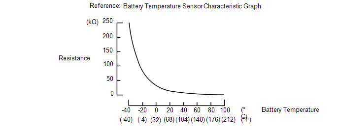
The battery temperature sensors are provided at 3 locations of the HV battery. The resistance of the thermistor, which is built into each battery temperature sensor, varies in accordance with changes in the HV battery temperature. The lower the battery temperature, the higher the thermistor resistance. Conversely, the higher the temperature, the lower the resistance. The battery voltage sensor uses the battery temperature sensors to detect the HV battery temperature, and sends the detected value to the hybrid vehicle control ECU. Based on the results of this detection, the hybrid vehicle control ECU controls the blower fan. (The blower fan starts when the HV battery temperature rises above a predetermined level.)
Temperature Sensor Identification Cross Reference Table:
| DTC Title Sensor | Battery Temperature Sensor | Techstream Display |
|---|---|---|
| A | 0 | 1 |
| B | 1 | 2 |
| C | 2 | 3 |
HINT:
Use the reference table above to determine which battery temperature sensor each DTC corresponds to. For example, sensor A in the DTC title column is battery temperature sensor 0. This sensor is displayed as Hybrid Battery Temperature 1 in the Data List.
| DTC No. | Detection Item | DTC Detection Condition | Trouble Area | MIL | Warning Indicate |
|---|---|---|---|---|---|
| P0A9B11 | Hybrid/EV Battery Temperature Sensor "A" Circuit Short to Ground | The battery temperature sensor is malfunctioning, its output voltage is lower than the specified value (short circuit) and the detected temperature is higher than the specified value. (1 trip detection logic) |
| Comes on | Master Warning Light: Comes on |
| P0A9B15 | Hybrid/EV Battery Temperature Sensor "A" Circuit Short to Auxiliary Battery or Open | The battery temperature sensor is malfunctioning, its output voltage is higher than the specified value (short to +B or open) and the detected temperature is lower than the specified value. (1 trip detection logic) |
| Comes on | Master Warning Light: Comes on |
| P0AC511 | Hybrid/EV Battery Temperature Sensor "B" Circuit Short to Ground | The battery temperature sensor is malfunctioning, its output voltage is lower than the specified value (short circuit) and the detected temperature is higher than the specified value. (1 trip detection logic) |
| Comes on | Master Warning Light: Comes on |
| P0AC515 | Hybrid/EV Battery Temperature Sensor "B" Circuit Short to Auxiliary Battery or Open | The battery temperature sensor is malfunctioning, its output voltage is higher than the specified value (short to +B or open) and the detected temperature is lower than the specified value. (1 trip detection logic) |
| Comes on | Master Warning Light: Comes on |
| P0ACA11 | Hybrid/EV Battery Temperature Sensor "C" Circuit Short to Ground | The battery temperature sensor is malfunctioning, its output voltage is lower than the specified value (short circuit) and the detected temperature is higher than the specified value. (1 trip detection logic) |
| Comes on | Master Warning Light: Comes on |
| P0ACA15 | Hybrid/EV Battery Temperature Sensor "C" Circuit Short to Auxiliary Battery or Open | The battery temperature sensor is malfunctioning, its output voltage is higher than the specified value (short to +B or open) and the detected temperature is lower than the specified value. (1 trip detection logic) |
| Comes on | Master Warning Light: Comes on |
| DTC No. | Data List |
|---|---|
| P0A9B11 | Hybrid Battery Temperature 1 to 3 |
| P0A9B15 | |
| P0AC511 | |
| P0AC515 | |
| P0ACA11 | |
| P0ACA15 |
HINT:
-
After checking for the above DTCs, check the hybrid system Data List item "Hybrid Battery Temperature" using the Techstream.
Temperature Displayed
Malfunction
Below -45°C (-49°F)
Open or +B short circuit
95°C (203°F) or more
GND short circuit
- If the vehicle as is left as is for 24 hours, the value of "Hybrid Battery Temperature" will be almost the same as the ambient temperature.
MONITOR DESCRIPTION
If a malfunction in the HV battery temperature sensor was detected, the hybrid vehicle control ECU will illuminate the MIL and set a DTC.
MONITOR STRATEGY
| Related DTCs | P0A9D (INF P0A9B11), P0AC7 (INF P0AC511), P0ACC (INF P0ACA11): Battery temperature sensor circuit malfunction (GND short) P0A9E (INF P0A9B15), P0AC8 (INF P0AC515), P0ACD (INF P0ACA15): Battery temperature sensor circuit malfunction (open) |
| Required sensors/components | Battery temperature sensor |
| Frequency of operation | Continuous |
| Duration | TMC's intellectual property |
| MIL operation | Immediately |
| Sequence of operation | None |
TYPICAL ENABLING CONDITIONS
| The monitor will run whenever the following DTCs are not stored | TMC's intellectual property |
| Other conditions belong to TMC's intellectual property | - |
TYPICAL MALFUNCTION THRESHOLDS
| TMC's intellectual property | - |
COMPONENT OPERATING RANGE
| Battery voltage sensor | DTC P0A9D (INF P0A9B11) is not detected DTC P0AC7 (INF P0AC511) is not detected DTC P0ACC (INF P0ACA11) is not detected DTC P0A9E (INF P0A9B15) is not detected DTC P0AC8 (INF P0AC515) is not detected DTC P0ACD (INF P0ACA15) is not detected |
CONFIRMATION DRIVING PATTERN
HINT:
-
After repair has been completed, clear the DTC and then check that the vehicle has returned to normal by performing the following All Readiness check procedure.
Click here
.gif)
-
When clearing the permanent DTCs, refer to the "CLEAR PERMANENT DTC" procedure.
Click here
- Connect the Techstream to the DLC3.
- Turn the power switch on (IG) and turn the Techstream on.
- Clear the DTCs (even if no DTCs are stored, perform the clear DTC procedure).
- Turn the power switch off and wait for 2 minutes or more.
- Turn the power switch on (IG) and turn the Techstream on.
-
With power switch on (IG) and wait for 5 seconds or more.[*1]
HINT:
[*1]: Normal judgment procedure.
The normal judgment procedure is used to complete DTC judgment and also used when clearing permanent DTCs.
- Enter the following menus: Powertrain / Hybrid Control / Utility / All Readiness.
-
Check the DTC judgment result.
HINT:
- If the judgment result shows NORMAL, the system is normal.
- If the judgment result shows ABNORMAL, the system has a malfunction.
- If the judgment result shows INCOMPLETE or N/A, perform the normal judgment procedure again.
WIRING DIAGRAM
Refer to the wiring diagram for DTC P0A9B2A.
Click here
CAUTION / NOTICE / HINT
CAUTION:
-
Before the following operations are conducted, take precautions to prevent electric shock by turning the power switch off, wearing insulated gloves, and removing the service plug grip from HV battery.
.png)
- Inspecting the high-voltage system
- Disconnecting the low voltage connector of the inverter with converter assembly
- Disconnecting the low voltage connector of the HV battery
-
To prevent electric shock, make sure to remove the service plug grip to cut off the high voltage circuit before servicing the vehicle.

-
After removing the service plug grip from the HV battery, put it in your pocket to prevent other technicians from accidentally reconnecting it while you are working on the high-voltage system.

-
After removing the service plug grip, wait for at least 10 minutes before touching any of the high-voltage connectors or terminals. After waiting for 10 minutes, check the voltage at the terminals in the inspection point in the inverter with converter assembly. The voltage should be 0 V before beginning work.
Click here

*a
Without waiting for 10 minutes
HINT:
Waiting for at least 10 minutes is required to discharge the high-voltage capacitor inside the inverter with converter assembly.
NOTICE:
After turning the power switch off, waiting time may be required before disconnecting the cable from the negative (-) auxiliary battery terminal. Therefore, make sure to read the disconnecting the cable from the negative (-) auxiliary battery terminal notices before proceeding with work.
Click here
PROCEDURE
| 1. | CHECK DTC OUTPUT (HYBRID CONTROL) |
(a) Connect the Techstream to the DLC3.
(b) Turn the power switch on (IG).
(c) Enter the following menus: Powertrain / Hybrid Control / Trouble Codes.
(d) Check for DTCs.
Powertrain > Hybrid Control > Trouble Codes| Result | Proceed to |
|---|---|
| P0AFC00, P0AFC96 or P308A12 is not output. | A |
| P0AFC00, P0AFC96 or P308A12 is output. | B |
(e) Turn the power switch off.
| B | .gif) | GO TO DTC CHART (HYBRID CONTROL SYSTEM) |
|
.gif)
| 2. | READ VALUE USING TECHSTREAM (HYBRID BATTERY TEMPERATURE) |
(a) Connect the Techstream to the DLC3.
(b) Turn the power switch on (IG).
(c) Enter the following menus: Powertrain / Hybrid Control / Data List / Hybrid Battery Temperature 1 to 3.
(d) Read the Data List.
Powertrain > Hybrid Control > Data List| Tester Display |
|---|
| Hybrid Battery Temperature 1 |
| Hybrid Battery Temperature 2 |
| Hybrid Battery Temperature 3 |
HINT:
A malfunctioning sensor (battery temperature sensor 0, 1 or 2) can be determined by comparing the output temperature of the 3 battery temperature sensors.
(e) Turn the power switch off.
|
| 3. | CHECK CONNECTOR CONNECTION CONDITION (BATTERY VOLTAGE SENSOR CONNECTION CONDITION) |
CAUTION:
Be sure to wear insulated gloves.
(a) Check that the service plug grip is not installed.
NOTICE:
After removing the service plug grip, do not turn the power switch on (READY), unless instructed by the repair manual because this may cause a malfunction.
(b) Remove the No. 1 hybrid battery exhaust duct.
Click here
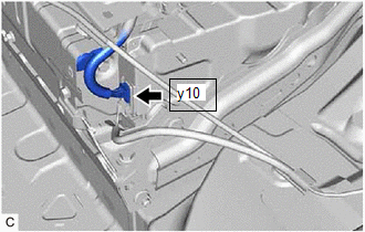
| (c) Check the connections of the y10 battery voltage sensor connector. Click here OK: The connector is connected securely and there are no contact problems. |
|
(d) Install the No. 1 hybrid battery exhaust duct.
| NG | | CONNECT SECURELY |
|
| 4. | CHECK HYBRID BATTERY THERMISTOR (BATTERY TEMPERATURE SENSOR) |
Click here
| OK | | REPLACE BATTERY VOLTAGE SENSOR |
|
| 5. | CHECK HARNESS AND CONNECTOR (BATTERY TEMPERATURE SENSOR) |
CAUTION:
Be sure to wear insulated gloves and protective goggles.
(a) Check that the service plug grip is not installed.
NOTICE:
After removing the service plug grip, do not turn the power switch on (READY), unless instructed by the repair manual because this may cause a malfunction.
(b) Remove the upper HV battery cover sub-assembly.
Click here
(c) Check the wire harness and connectors of the battery temperature sensors for abnormalities by sight and touch.
Specified Condition:
There are no open or short circuits in the wire harness and connectors. There are no short circuits to other wire harnesses.
(d) Install the upper HV battery cover sub-assembly.
| OK | | REPLACE HYBRID BATTERY THERMISTOR |
| NG | | REPAIR HARNESS OR CONNECTOR (BATTERY TEMPERATURE SENSOR) |
READ NEXT:
 Hybrid/EV Battery Temperature Sensor "A" Voltage Out of Range (P0A9B1C,P0AC51C,P0ACA1C)
DESCRIPTION These DTCs will be stored if the difference between the maximum and minimum output of each battery temperature sensors exceeds a certain amount and if the output of one battery temperature
Hybrid/EV Battery Temperature Sensor "A" Signal Stuck In Range (P0A9B2A,P0AC52A,P0ACA2A,P306562)
DESCRIPTION Refer to the description for DTC P0A9B11. Click here DTC No. Detection Item DTC Detection Condition Trouble Area MIL Warning Indicate P0A9B2A Hybrid/EV Battery Tempera
Hybrid/EV Battery Positive Contactor Circuit Stuck Closed (P0AA000)
DTC SUMMARY MALFUNCTION DESCRIPTION The hybrid vehicle control ECU detects a stuck closed malfunction of a system main relay on the HV battery positive (+) terminal side. The cause of this malfunction
SEE MORE:
System Diagram
SYSTEM DIAGRAM Transmitting ECU (Transmitter) Receiving ECU Signal Communication Method Skid control ECU (brake actuator assembly) Steering angle sensor Steering angle sensor request signal CAN communication line Steering angle sensor Skid control ECU (brake actuator a
Removal
REMOVAL CAUTION / NOTICE / HINT The necessary procedures (adjustment, calibration, initialization, or registration) that must be performed after parts are removed and installed, or replaced during rear axle carrier sub-assembly removal/installation are shown below. Necessary Procedures After Parts R
