Lexus ES: Hybrid/EV Battery Current Sensor "A" Signal Bias Level Out of Range / Zero Adjustment Failure (P0ABF28)
DESCRIPTION
Refer to the description for DTC P0ABF11.
Click here .gif)
| DTC No. | Detection Item | DTC Detection Condition | Trouble Area | MIL | Warning Indicate |
|---|---|---|---|---|---|
| P0ABF28 | Hybrid/EV Battery Current Sensor "A" Signal Bias Level Out of Range / Zero Adjustment Failure | The offset value of the battery current sensor is excessively large. (1 trip detection logic) |
| Comes on | Master Warning Light: Comes on |
| DTC No. | Data List |
|---|---|
| P0ABF28 |
|
HINT:
*1: The value of "Hybrid Battery Current for Hybrid Battery Control" usually changes by 4 A or more while the vehicle is accelerating and decelerating.
MONITOR DESCRIPTION
If the battery voltage sensor detects a malfunction in the battery current sensor, the hybrid vehicle control ECU will illuminate the MIL and store a DTC.
MONITOR STRATEGY
| Related DTCs | P0AC0 (INF P0ABF28): Current sensor malfunction |
| Required sensors/components | Battery current sensor |
| Frequency of operation | Continuous |
| Duration | TMC's intellectual property |
| MIL operation | 1 driving cycle |
| Sequence of operation | None |
TYPICAL ENABLING CONDITIONS
| The monitor will run whenever the following DTCs are not stored | TMC's intellectual property |
| Other conditions belong to TMC's intellectual property | - |
TYPICAL MALFUNCTION THRESHOLDS
| TMC's intellectual property | - |
COMPONENT OPERATING RANGE
| Battery voltage sensor | DTC P0AC0 (INF P0ABF28) is not detected |
CONFIRMATION DRIVING PATTERN
HINT:
-
After repair has been completed, clear the DTC and then check that the vehicle has returned to normal by performing the following All Readiness check procedure.
Click here
-
When clearing the permanent DTCs, refer to the "CLEAR PERMANENT DTC" procedure.
Click here
- Connect the Techstream to the DLC3.
- Turn the power switch on (IG) and turn the Techstream on.
- Clear the DTCs (even if no DTCs are stored, perform the clear DTC procedure).
- Turn the power switch off and wait for 2 minutes or more.
- Drive the vehicle on urban roads for approximately 10 minutes.[*1]
- Turn the power switch off and wait for 2 minutes or more.[*2]
- Turn the power switch on (IG) and turn the Techstream on.[*3]
-
With power switch on (IG) and wait for 10 seconds or more.[*4]
HINT:
[*1] to [*4]: Normal judgment procedure.
The normal judgment procedure is used to complete DTC judgment and also used when clearing permanent DTCs.
- Enter the following menus: Powertrain / Hybrid Control / Utility / All Readiness.
-
Check the DTC judgment result.
HINT:
- If the judgment result shows NORMAL, the system is normal.
- If the judgment result shows ABNORMAL, the system has a malfunction.
- If the judgment result shows INCOMPLETE or N/A, perform the normal judgment procedure again.
WIRING DIAGRAM
Refer to the wiring diagram for DTC P0ABF11.
Click here
CAUTION / NOTICE / HINT
CAUTION:
-
Before the following operations are conducted, take precautions to prevent electric shock by turning the power switch off, wearing insulated gloves, and removing the service plug grip from HV battery.
.png)
- Inspecting the high-voltage system
- Disconnecting the low voltage connector of the inverter with converter assembly
- Disconnecting the low voltage connector of the HV battery
-
To prevent electric shock, make sure to remove the service plug grip to cut off the high voltage circuit before servicing the vehicle.

-
After removing the service plug grip from the HV battery, put it in your pocket to prevent other technicians from accidentally reconnecting it while you are working on the high-voltage system.

-
After removing the service plug grip, wait for at least 10 minutes before touching any of the high-voltage connectors or terminals. After waiting for 10 minutes, check the voltage at the terminals in the inspection point in the inverter with converter assembly. The voltage should be 0 V before beginning work.
Click here

*a
Without waiting for 10 minutes
HINT:
Waiting for at least 10 minutes is required to discharge the high-voltage capacitor inside the inverter with converter assembly.
NOTICE:
After turning the power switch off, waiting time may be required before disconnecting the cable from the negative (-) auxiliary battery terminal. Therefore, make sure to read the disconnecting the cable from the negative (-) auxiliary battery terminal notices before proceeding with work.
Click here
PROCEDURE
| 1. | CHECK DTC OUTPUT (HYBRID CONTROL) |
(a) Connect the Techstream to the DLC3.
(b) Turn the power switch on (IG).
(c) Enter the following menus: Powertrain / Hybrid Control / Trouble Codes.
(d) Check for DTCs.
Powertrain > Hybrid Control > Trouble Codes| Result | Proceed to |
|---|---|
| P0AFC00, P0AFC96 or P0A9563 is not output. | A |
| P0AFC00, P0AFC96 or P0A9563 is output. | B |
(e) Turn the power switch off.
| B | .gif) | GO TO DTC CHART (HYBRID CONTROL SYSTEM) |
|
.gif)
| 2. | CHECK HARNESS AND CONNECTOR (BATTERY VOLTAGE SENSOR - HV BATTERY JUNCTION BLOCK ASSEMBLY) |
Click here
| NG | | REPLACE HYBRID BATTERY THERMISTOR |
|
| 3. | CHECK HV BATTERY JUNCTION BLOCK ASSEMBLY (BATTERY CURRENT SENSOR (IB)) |
CAUTION:
Be sure to wear insulated gloves.
(a) Check that the service plug grip is not installed.
NOTICE:
After removing the service plug grip, do not turn the power switch on (READY), unless instructed by the repair manual because this may cause a malfunction.
(b) Remove the No. 1 hybrid battery exhaust duct.
Click here
(c) Connect the cable to the negative (-) auxiliary battery terminal.
(d) Turn the power switch on (IG).
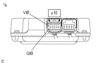
| (e) Using a toyota electrical tester set to 40 V, measure the VIB voltage according to the value(s) in the table below.
NOTICE:
|
|
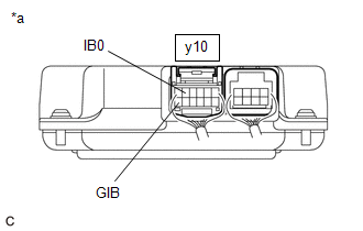
| (f) Using a toyota electrical tester set to 4 V, measure the IB0 voltage according to the value(s) in the table below.
NOTICE: Be sure to set the toyota electrical tester to 4 V when performing this test. |
|
(g) Compare the measured values of the IB0 terminal voltage and VIB terminal voltage using the following formula:
| IB0 voltage - VIB Voltage / 2 = less than 0.081 V |
| IB0 voltage - VIB Voltage / 2 = -0.081 V or higher |
| Result | Proceed to |
|---|---|
| Within the specified range above | A |
| Other than above | B |
(h) Turn the power switch off.
(i) Disconnect the cable from the negative (-) auxiliary battery terminal.
(j) Install the No. 1 hybrid battery exhaust duct.
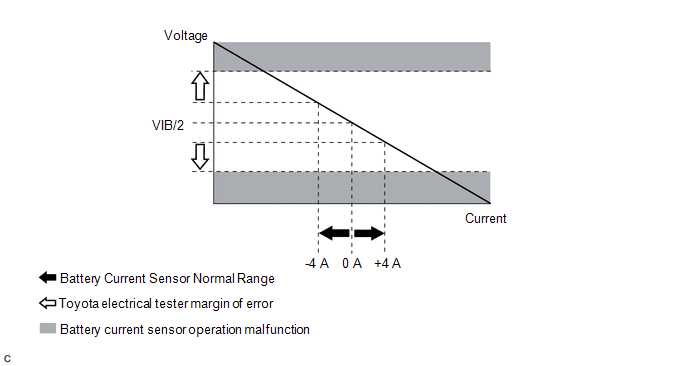
HINT:
When the power switch is on (IG) the actual current will be approximately 0 A. The following graph shows the relation of the actual output voltage of the battery current sensor terminal IB0 and actual current used for DTC judgment.
| B | | REPLACE HV BATTERY JUNCTION BLOCK ASSEMBLY |
|
| 4. | REPLACE BATTERY VOLTAGE SENSOR |
Click here
|
| 5. | SIMULATION TEST |
(a) Connect the Techstream to the DLC3.
(b) Turn the power switch on (IG).
(c) Enter the following menus: Powertrain / Hybrid Control / Trouble Codes.
(d) Clear the DTCs and freeze frame data.
Powertrain > Hybrid Control > Clear DTCs(e) Drive the vehicle on urban roads for approximately 10 minutes.
(f) Turn the power switch off and wait for 2 minutes or more.
(g) Turn the power switch on (IG) and wait for 10 seconds or more.
|
| 6. | RECONFIRM DTC OUTPUT (HYBRID CONTROL) |
(a) Connect the Techstream to the DLC3.
(b) Turn the power switch on (IG).
(c) Enter the following menus: Powertrain / Hybrid Control / Trouble Codes.
(d) Read output DTCs.
Powertrain > Hybrid Control > Trouble Codes| Result | Proceed to |
|---|---|
| P0ABF28 is not output. | A |
| P0ABF28 is output. | B |
(e) Turn the power switch off.
| A | | END |
| B | | REPLACE HV BATTERY JUNCTION BLOCK ASSEMBLY |
READ NEXT:
 Hybrid/EV Battery Current Sensor "A" Signal Stuck In Range (P0ABF2A)
DESCRIPTION Refer to the description for DTC P0ABF11. Click here DTC No. Detection Item DTC Detection Condition Trouble Area MIL Warning Indicate P0ABF2A Hybrid/EV Battery Current
Hybrid/EV Battery Positive Contactor Circuit Short to Ground (P0AD911)
DESCRIPTION Refer to the description for DTC P0AE411. Click here DTC No. Detection Item DTC Detection Condition Trouble Area MIL Warning Indicate P0AD911 Hybrid/EV Battery Positiv
Hybrid/EV Battery Positive Contactor Circuit Short to Auxiliary Battery or Open (P0AD915)
DESCRIPTION Refer to the description for DTC P0AE411. Click here DTC No. Detection Item DTC Detection Condition Trouble Area MIL Warning Indicate P0AD915 Hybrid/EV Battery Positiv
SEE MORE:
How To Proceed With Troubleshooting
CAUTION / NOTICE / HINT HINT:
Use the following procedure to troubleshoot the vehicle proximity notification system.
*: Use the Techstream.
PROCEDURE 1. VEHICLE BROUGHT TO WORKSHOP
NEXT 2. CUSTOMER PROBLEM ANALYSIS AND SYMPTOM CHECK HINT:
In troubleshoot
Precaution
PRECAUTION PRECAUTION FOR DISCONNECTING CABLE FROM NEGATIVE AUXILIARY BATTERY TERMINAL NOTICE: When disconnecting the cable from the negative (-) auxiliary battery terminal, initialize the following system(s) after the cable is reconnected: System See Procedure Lane Control System (for HV M
