Lexus ES: Hybrid/EV Battery Block 1 Voltage Difference Out of Range (P1CBE1E,...,P1CFD1E)
DESCRIPTION
Refer to the description for DTC P1AC000.
Click here .gif)
| DTC No. | Detection Item | DTC Detection Condition | Trouble Area | MIL | Warning Indicate |
|---|---|---|---|---|---|
| P1CBE1E | Hybrid/EV Battery Block 1 Voltage Difference Out of Range | An internal malfunction of the HV battery is detected. The difference in voltage of each battery block is higher than the specified value. (1 trip detection logic) |
| Comes on | Master Warning Light: Comes on |
| P1CBF1E | Hybrid/EV Battery Block 2 Voltage Difference Out of Range | An internal malfunction of the HV battery is detected. The difference in voltage of each battery block is higher than the specified value. (1 trip detection logic) |
| Comes on | Master Warning Light: Comes on |
| P1CC01E | Hybrid/EV Battery Block 3 Voltage Difference Out of Range | An internal malfunction of the HV battery is detected. The difference in voltage of each battery block is higher than the specified value. (1 trip detection logic) |
| Comes on | Master Warning Light: Comes on |
| P1CC11E | Hybrid/EV Battery Block 4 Voltage Difference Out of Range | An internal malfunction of the HV battery is detected. The difference in voltage of each battery block is higher than the specified value. (1 trip detection logic) |
| Comes on | Master Warning Light: Comes on |
| P1CC21E | Hybrid/EV Battery Block 5 Voltage Difference Out of Range | An internal malfunction of the HV battery is detected. The difference in voltage of each battery block is higher than the specified value. (1 trip detection logic) |
| Comes on | Master Warning Light: Comes on |
| P1CC31E | Hybrid/EV Battery Block 6 Voltage Difference Out of Range | An internal malfunction of the HV battery is detected. The difference in voltage of each battery block is higher than the specified value. (1 trip detection logic) |
| Comes on | Master Warning Light: Comes on |
| P1CC41E | Hybrid/EV Battery Block 7 Voltage Difference Out of Range | An internal malfunction of the HV battery is detected. The difference in voltage of each battery block is higher than the specified value. (1 trip detection logic) |
| Comes on | Master Warning Light: Comes on |
| P1CC51E | Hybrid/EV Battery Block 8 Voltage Difference Out of Range | An internal malfunction of the HV battery is detected. The difference in voltage of each battery block is higher than the specified value. (1 trip detection logic) |
| Comes on | Master Warning Light: Comes on |
| P1CC61E | Hybrid/EV Battery Block 9 Voltage Difference Out of Range | An internal malfunction of the HV battery is detected. The difference in voltage of each battery block is higher than the specified value. (1 trip detection logic) |
| Comes on | Master Warning Light: Comes on |
| P1CC71E | Hybrid/EV Battery Block 10 Voltage Difference Out of Range | An internal malfunction of the HV battery is detected. The difference in voltage of each battery block is higher than the specified value. (1 trip detection logic) |
| Comes on | Master Warning Light: Comes on |
| P1CFD1E | Hybrid/EV Battery Block 11 Voltage Difference Out of Range | An internal malfunction of the HV battery is detected. The difference in voltage of each battery block is higher than the specified value. (1 trip detection logic) |
| Comes on | Master Warning Light: Comes on |
HINT:
- These DTCs can be stored after clearing DTCs and driving the vehicle for approximately 10 minutes.
-
These DTCs are stored when a malfunction is detected in the HV battery or a battery voltage sensor. However, depending on the driving conditions, the malfunction may not be reproduced if the condition of the HV battery changes.
-
When the HV battery is malfunctioning:
-
- Voltage of 1 or more of the battery blocks has dropped.
- Voltage of all battery blocks is output randomly with no certain pattern.
-
- Voltage of 1 or more of the battery blocks has dropped.
-
When the battery voltage sensor is malfunctioning:
- - While current is flowing to or from the HV battery, the voltage of a specific HV battery block will fluctuates.
-
When the HV battery is malfunctioning:
-
In order to ensure HV battery performance, appropriate cooling performance must be maintained. Perform the following items as necessary. If cooling performance has decreased and "Maintenance Required for Traction Battery Cooling Parts See Owner's Manual" is displayed on the multi-information display, make sure to perform the following items:
- Make sure the air intake port is not blocked.
- Make sure there are no gaps between the connecting parts of the ducts.
-
Clean the No. 1 HV battery intake filter.
- Clear the DTCs to reset the learning values even if no DTCs are stored.
| DTC No. | Data List |
|---|---|
| P1CBE1E |
|
| P1CBF1E | |
| P1CC01E | |
| P1CC11E | |
| P1CC21E | |
| P1CC31E | |
| P1CC41E | |
| P1CC51E | |
| P1CC61E | |
| P1CC71E | |
| P1CFD1E |
HINT:
- *1: Under normal conditions, the values of Hybrid Battery Block 1, 2, 9, 10 and 11 Voltage will be approximately 16 V and Hybrid Battery Block 3, 4, 5, 6, 7 and 8 Voltage will be approximately 32 V.
- If there is a short or open in a battery block voltage detection line, the value of Hybrid Battery Block Voltage for the corresponding battery block will be lower than 8 V.
- The Data List items Internal Resistance 1 to 11 indicate internal resistance correction values used by the hybrid vehicle control ECU to detect malfunctions of the HV battery.
The following items can be helpful when performing repairs:
- Ready Signal
- Vehicle Speed
- Accelerator Position
- Shift Position
- Engine Speed
- Hybrid Battery Voltage
- Hybrid Battery Current
- BATT Voltage
- Hybrid Battery SOC of Immediately after IG ON
- Hybrid Battery Maximum SOC
- Hybrid Battery Minimum SOC
- Total Distance Traveled
- Distance from DTC Cleared
- Engine Run Time
- Hybrid Battery Voltage Low
MONITOR DESCRIPTION
If there is an abnormal internal resistance or voltage in the battery blocks, the battery voltage sensor determines that a malfunction has occurred. When the malfunction detection condition is satisfied, the hybrid vehicle control ECU will illuminate the MIL and store a DTC.
MONITOR STRATEGY
| Related DTCs | P3011 (INF P1CBE1E), P3012 (INF P1CBF1E), P3013 (INF P1CC01E), P3014 (INF P1CC11E), P3015 (INF P1CC21E), P3016 (INF P1CC31E), P3017 (INF P1CC41E), P3018 (INF P1CC51E), P3019 (INF P1CC61E), P3020 (INF P1CC71E), P3021 (INF P1CFD1E): Battery cell malfunction |
| Required sensors/components | Battery voltage sensor |
| Frequency of operation | Continuous |
| Duration | TMC's intellectual property |
| MIL operation | Immediately |
| Sequence of operation | None |
TYPICAL ENABLING CONDITIONS
| The monitor will run whenever the following DTCs are not stored | TMC's intellectual property |
| Other conditions belong to TMC's intellectual property | - |
TYPICAL MALFUNCTION THRESHOLDS
| TMC's intellectual property | - |
COMPONENT OPERATING RANGE
| Battery voltage sensor | DTC P3011 (INF P1CBE1E) is not detected DTC P3012 (INF P1CBF1E) is not detected DTC P3013 (INF P1CC01E) is not detected DTC P3014 (INF P1CC11E) is not detected DTC P3015 (INF P1CC21E) is not detected DTC P3016 (INF P1CC31E) is not detected DTC P3017 (INF P1CC41E) is not detected DTC P3018 (INF P1CC51E) is not detected DTC P3019 (INF P1CC61E) is not detected DTC P3020 (INF P1CC71E) is not detected DTC P3021 (INF P1CFD1E) is not detected |
CONFIRMATION DRIVING PATTERN
HINT:
-
After repair has been completed, clear the DTC and then check that the vehicle has returned to normal by performing the following All Readiness check procedure.
Click here
-
When clearing the permanent DTCs, refer to the "CLEAR PERMANENT DTC" procedure.
Click here
- Connect the Techstream to the DLC3.
- Turn the power switch on (IG) and turn the Techstream on.
- Clear the DTCs (even if no DTCs are stored, perform the clear DTC procedure).
- Turn the power switch off and wait for 2 minutes or more.
- Turn the power switch on (IG) and turn the Techstream on.
-
Drive the vehicle on urban roads for approximately 10 minutes.[*1]
HINT:
- This DTC may not be stored if the vehicle is stopped or being driven at a constant speed.
-
[*1]: Normal judgment procedure.
The normal judgment procedure is used to complete DTC judgment and also used when clearing permanent DTCs.
- Enter the following menus: Powertrain / Hybrid Control / Utility / All Readiness.
-
Check the DTC judgment result.
HINT:
- If the judgment result shows NORMAL, the system is normal.
- If the judgment result shows ABNORMAL, the system has a malfunction.
- If the judgment result shows INCOMPLETE or N/A, perform the normal judgment procedure again.
CAUTION / NOTICE / HINT
CAUTION:
-
Before the following operations are conducted, take precautions to prevent electric shock by turning the power switch off, wearing insulated gloves, and removing the service plug grip from HV battery.
.png)
- Inspecting the high-voltage system
- Disconnecting the low voltage connector of the inverter with converter assembly
- Disconnecting the low voltage connector of the HV battery
-
To prevent electric shock, make sure to remove the service plug grip to cut off the high voltage circuit before servicing the vehicle.

-
After removing the service plug grip from the HV battery, put it in your pocket to prevent other technicians from accidentally reconnecting it while you are working on the high-voltage system.

-
After removing the service plug grip, wait for at least 10 minutes before touching any of the high-voltage connectors or terminals. After waiting for 10 minutes, check the voltage at the terminals in the inspection point in the inverter with converter assembly. The voltage should be 0 V before beginning work.
Click here

*a
Without waiting for 10 minutes
HINT:
Waiting for at least 10 minutes is required to discharge the high-voltage capacitor inside the inverter with converter assembly.
-
Make sure to insulate the high-voltage connectors and terminals of the HV battery with insulating tape after removing it.
If the HV battery stored without insulating the connectors and terminals, electric shock or fire may result.
-
When disposing of an HV battery, make sure to return it through an authorized collection agent who is capable of handling it safely. If the HV battery is returned via the manufacturer specified route, it will be returned properly and in a safe manner by an authorized collection agent.
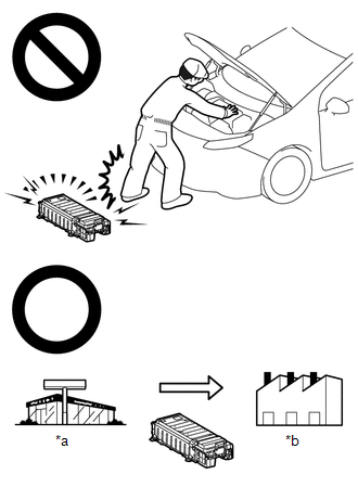
*a
Dealer
*b
Battery Collection Agent
- Accidents such as electric shock may result if the HV battery is disposed of improperly or abandoned. Therefore, make sure to return all HV batteries through an authorized collection agent.
-
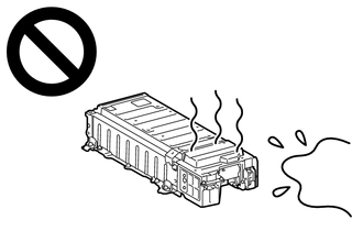
After removing the HV battery, keep it away from water. Exposure to water may cause the HV battery to produce heat, resulting in a fire.
NOTICE:
After turning the power switch off, waiting time may be required before disconnecting the cable from the negative (-) auxiliary battery terminal. Therefore, make sure to read the disconnecting the cable from the negative (-) auxiliary battery terminal notices before proceeding with work.
Click here
PROCEDURE
| 1. | CHECK DTC OUTPUT (HYBRID CONTROL) |
(a) Connect the Techstream to the DLC3.
(b) Turn the power switch on (IG).
(c) Enter the following menus: Powertrain / Hybrid Control / Trouble Codes.
(d) Check for DTCs.
Powertrain > Hybrid Control > Trouble Codes| Result | Proceed to |
|---|---|
| P0AFC00, P0AFC96, P308A12 or P0AFC62 is not output. | A |
| P0AFC00, P0AFC96, P308A12 or P0AFC62 is output. | B |
(e) Turn the power switch off.
| B | .gif) | GO TO DTC CHART (HYBRID CONTROL SYSTEM) |
|
.gif)
| 2. | CHECK FREEZE FRAME DATA |
Click here
| Result | Proceed to |
|---|---|
| On the HV battery blocks 3 to 8, one of the conditions in the table above is met. | A |
| Other than above | B |
| B | | GO TO STEP 5 |
|
| 3. | CHECK TOTAL DISTANCE DRIVEN |
(a) Read the odometer to check the total distance the vehicle has been driven.
| Result | Proceed to | |
|---|---|---|
| Total distance driven is less than 200000 km (124280 mile) | A | |
| Total distance driven is 200000 km (124280 mile) or more | Current total distance driven - total distance driven when hybrid battery terminal block replaced = less than 200000 km (124280 mile) *1 | |
| Other than above | B | |
HINT:
*1: If the hybrid battery terminal block has been replaced, use the total distance driven since it was replaced.
| A | | REPLACE HV BATTERY |
|
| 4. | REPLACE HV BATTERY |
Click here
| NEXT | | REPLACE HYBRID BATTERY TERMINAL BLOCK |
| 5. | CHECK FREEZE FRAME DATA |
Click here
| Result | Proceed to |
|---|---|
| Either of the following conditions is met: 1. All conditions in table 1 are met. 2. All conditions in table 2 are met. | A |
| Other than above | B |
| A | | REPLACE BATTERY VOLTAGE SENSOR |
|
| 6. | READ VALUE USING TECHSTREAM (HYBRID BATTERY BLOCK VOLTAGE) |
(a) Connect the Techstream to the DLC3.
(b) Turn the power switch on (READY).
(c) Allow the engine to idle until Coolant Temperature is 75°C (167°F) or higher.
(d) With the vehicle stopped, apply the parking brake.
(e) Turn the A/C switch off.
(f) Enter the following menus: Powertrain / Hybrid Control / Data List / Hybrid Battery Block 1 to 3 Voltage, Hybrid Battery Block 8 to 10 Voltage.
NOTICE:
Select "Hybrid Battery Block 1 to 3 Voltage" and "Hybrid Battery Block 8 to 10 Voltage" only. (Do not select any other Data List items.)
Powertrain > Hybrid Control > Data List| Tester Display |
|---|
| Hybrid Battery Block 1 Voltage |
| Hybrid Battery Block 2 Voltage |
| Hybrid Battery Block 3 Voltage |
| Hybrid Battery Block 8 Voltage |
| Hybrid Battery Block 9 Voltage |
| Hybrid Battery Block 10 Voltage |
| Hybrid Battery Block Voltage | Circuit Battery Block |
|---|---|
| Hybrid Battery Block 1 Voltage | Circuit A Battery Block |
| Hybrid Battery Block 2 Voltage | Circuit B Battery Block |
| Hybrid Battery Block 3 Voltage | Circuit C Battery Block |
| Hybrid Battery Block 8 Voltage | Circuit C Battery Block |
| Hybrid Battery Block 9 Voltage | Circuit B Battery Block |
| Hybrid Battery Block 10 Voltage | Circuit A Battery Block |
(g) Ensure the safety of the areas in front and at the back of the vehicle.
(h) Move the shift lever to D and depress both the accelerator pedal and brake pedal at the same time.
(i) Check the voltage of each "Hybrid Battery Block Voltage" of "Hybrid Battery Block 1 to 3 Voltage" and "Hybrid Battery Block 8 to 10 Voltage" in the Data List with the power switch on (READY).
NOTICE:
When comparing the voltage of a circuit C battery block with that of a circuit A battery block or circuit B battery block, use half of the displayed voltage value for the circuit C battery block.
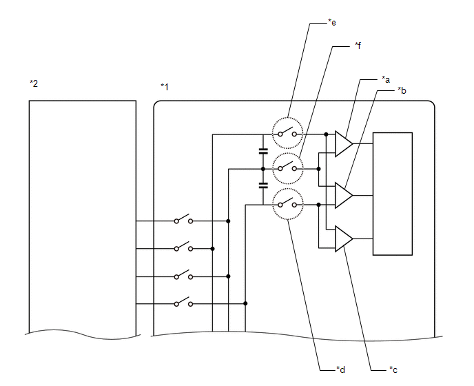
| *1 | Battery Voltage Sensor | *2 | HV Battery |
| *a | Circuit A Battery Block | *b | Circuit B Battery Block |
| *c | Circuit C Battery Block | *d | Judged in Table 1 |
| *e | Judged in Table 2 | *f | Judged in Table 3 |
| Circuit A Battery Block | Circuit B Battery Block | Circuit C Battery Block | Condition |
|---|---|---|---|
| Hybrid Battery Block 1 Voltage | Hybrid Battery Block 2 Voltage | Hybrid Battery Block 3 Voltage | Compared to value of "Hybrid Battery Block 1 Voltage", values of "Hybrid Battery Block 2 Voltage" and "Hybrid Battery Block 3 Voltage" fluctuate. |
| Hybrid Battery Block 10 Voltage | Hybrid Battery Block 9 Voltage | Hybrid Battery Block 8 Voltage | Compared to value of "Hybrid Battery Block 10 Voltage", values of "Hybrid Battery Block 8 Voltage" and "Hybrid Battery Block 9 Voltage" fluctuate. |
| Circuit A Battery Block | Circuit B Battery Block | Circuit C Battery Block | Condition |
|---|---|---|---|
| Hybrid Battery Block 1 Voltage | Hybrid Battery Block 2 Voltage | Hybrid Battery Block 3 Voltage | Compared to value of "Hybrid Battery Block 2 Voltage", values of "Hybrid Battery Block 1 Voltage" and "Hybrid Battery Block 3 Voltage" fluctuate. |
| Hybrid Battery Block 10 Voltage | Hybrid Battery Block 9 Voltage | Hybrid Battery Block 8 Voltage | Compared to value of "Hybrid Battery Block 9 Voltage", values of "Hybrid Battery Block 8 Voltage" and "Hybrid Battery Block 10 Voltage" fluctuate. |
| Circuit A Battery Block | Circuit B Battery Block | Circuit C Battery Block | Condition |
|---|---|---|---|
| Hybrid Battery Block 1 Voltage | Hybrid Battery Block 2 Voltage | Hybrid Battery Block 3 Voltage | Compared to value of "Hybrid Battery Block 3 Voltage", values of "Hybrid Battery Block 1 Voltage" and "Hybrid Battery Block 2 Voltage" fluctuate. |
| Hybrid Battery Block 10 Voltage | Hybrid Battery Block 9 Voltage | Hybrid Battery Block 8 Voltage | Compared to value of "Hybrid Battery Block 8 Voltage", values of "Hybrid Battery Block 9 Voltage" and "Hybrid Battery Block 10 Voltage" fluctuate. |
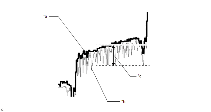
| *a | Normal | *b | Abnormal |
| *c | Fluctuation of 0.2 V or more | - | - |
HINT:
- If an internal malfunction occurs in the battery voltage sensor, the voltage of a specific hybrid battery block will fluctuate 0.2 V or more.
- As changes in the voltage of hybrid battery blocks are difficult to see when the HV battery current is 0 A, read the Data List while the HV battery is being charged or discharged.
- By displaying the Data List items for the corresponding circuit A battery block, circuit B battery block and circuit C battery block simultaneously, judgment can be performed more easily.
- Make sure to set the graph display so that each graduation on the horizontal axis (time) indicates approximately 10 seconds.
| Result | Proceed to |
|---|---|
| All conditions in Table 1, Table 2 or Table 3 are met. | A |
| Other than above | B |
(j) Turn the power switch off.
| A | | REPLACE BATTERY VOLTAGE SENSOR |
|
| 7. | CHECK DTC OUTPUT (HYBRID CONTROL) |
(a) Connect the Techstream to the DLC3.
(b) Turn the power switch on (IG).
(c) Enter the following menus: Powertrain / Hybrid Control / Trouble Codes.
(d) Check for DTCs.
Powertrain > Hybrid Control > Trouble Codes| Result | Proceed to |
|---|---|
| P1CFD1E, P302100 or P30211E is not output. | A |
| P1CFD1E, P302100 or P30211E is output. | B |
(e) Turn the power switch off.
| B | | GO TO STEP 10 |
|
| 8. | CHECK TOTAL DISTANCE DRIVEN |
(a) Read the odometer to check the total distance the vehicle has been driven.
| Result | Proceed to | |
|---|---|---|
| Total distance driven is less than 200000 km (124280 mile) | A | |
| Total distance driven is 200000 km (124280 mile) or more | Current total distance driven - total distance driven when hybrid battery terminal block replaced = less than 200000 km (124280 mile) *1 | |
| Other than above | B | |
HINT:
*1: If the hybrid battery terminal block has been replaced, use the total distance driven since it was replaced.
| A | | REPLACE HV BATTERY |
|
| 9. | REPLACE HV BATTERY |
Click here
| NEXT | | REPLACE HYBRID BATTERY TERMINAL BLOCK |
| 10. | REPLACE HV BATTERY |
Click here
| NEXT | | REPLACE HYBRID BATTERY TERMINAL BLOCK |
READ NEXT:
 PCU Interlock Circuit Open (P1CE213,P1CE292)
DTC SUMMARY MALFUNCTION DESCRIPTION The hybrid vehicle control ECU detects that a safety device (interlock) is operated or that there is an open circuit in the detection circuit. (Even if an open circ
IGB Signal Circuit Short to Auxiliary Battery (P1CFA12)
DESCRIPTION The hybrid vehicle control ECU monitors the IGB signal received from the certification ECU (smart key ECU assembly). When an error is detected in the IGB signal, this DTC is stored. DTC
Throttle/Pedal Position Sensor/Switch "D" Circuit Short to Auxiliary Battery (P212012,...,P21382B)
DTC SUMMARY MALFUNCTION DESCRIPTION The hybrid vehicle control ECU calculates the accelerator pedal opening angle based on the output voltage of the main sensor (VPA) and sub sensor (VPA2) of the acce
SEE MORE:
Open in One Side of Bus 4 Branch Line
DESCRIPTION When the CAN bus main lines are normal (no open, short to ground, short to +B or short between lines) and there is an ECU or sensor on the "Communication Bus Check" screen that is indicated as not communicating or whose connection status on the "Communication Bus Check" screen changes in
Reassembly
REASSEMBLY PROCEDURE 1. INSTALL FRONT DIFFERENTIAL CASE FRONT TAPERED ROLLER BEARING (INNER RACE) (a) Using SST and a press, install a new front differential case front tapered roller bearing (inner race) to the differential case assembly. SST: 09316-20011 SST: 09513-36040 NOTICE:
Do not dam
