Lexus ES: Front Passenger Side Power Window does not Operate with Front Passenger Side Power Window Switch
DESCRIPTION
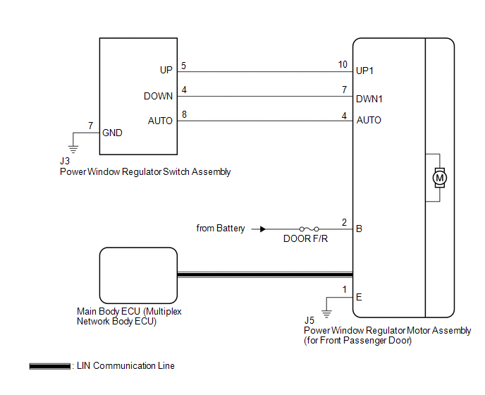
When the engine switch is on (IG), the power window regulator motor assembly (for front passenger door) is operated by the power window regulator switch assembly. The power window regulator motor assembly (for front passenger door) has motor, regulator, and ECU functions.
WIRING DIAGRAM
CAUTION / NOTICE / HINT
NOTICE:
-
The power window control system uses the LIN communication system. Inspect the communication function by following How to Proceed with Troubleshooting. Troubleshoot the power window control system after confirming that the communication system is functioning properly.
Click here
.gif)
-
If the power window regulator motor assembly (for front passenger door) has been replaced with a new one, initialize the power window control system.
Click here
- Check that the window lock switch is off before performing the following procedure.
- Inspect the fuses for circuits related to this system before performing the following procedure.
-
Before replacing the main body ECU (multiplex network body ECU), refer to Registration.
Click here
PROCEDURE
| 1. | READ VALUE USING TECHSTREAM (MAIN BODY) |
(a) Connect the Techstream to the DLC3.
(b) Turn the engine switch on (IG).
(c) Turn the Techstream on.
(d) Enter the following menus: Body Electrical / Main Body / Data List.
(e) Read the Data List according to the display on the Techstream.
Body Electrical > Main Body > Data List| Tester Display | Measurement Item | Range | Normal Condition | Diagnostic Note |
|---|---|---|---|---|
| Communication P-Door Motor | Connection status between power window regulator motor assembly (for front passenger door) and main body ECU (multiplex network body ECU) | STOP or OK | STOP: Communication stopped OK: Normal communication | - |
| Tester Display |
|---|
| Communication P-Door Motor |
OK:
OK is displayed for each Data List item above.
| NG | .gif) | GO TO LIN COMMUNICATION SYSTEM (Proceed to How to Proceed with Troubleshooting) |
|
.gif)
| 2. | READ VALUE USING TECHSTREAM (P-DOOR MOTOR) |
(a) Enter the following menus: Body Electrical / P-Door Motor / Data List.
(b) Read the Data List according to the display on the Techstream.
Body Electrical > P-Door Motor > Data List| Tester Display | Measurement Item | Range | Normal Condition | Diagnostic Note |
|---|---|---|---|---|
| P Door P/W Up SW | Front passenger door power window manual up switch signal | OFF or ON | OFF: Front passenger door power window manual up switch not being operated ON: Front passenger door power window manual up switch being operated | - |
| P Door P/W Down SW | Front passenger door power window manual down switch signal | OFF or ON | OFF: Front passenger door power window manual down switch not being operated ON: Front passenger door power window manual down switch being operated | - |
| Tester Display |
|---|
| P Door P/W Up SW |
| P Door P/W Down SW |
OK:
On the Techstream screen, ON or OFF is displayed accordingly.
| NG | | GO TO STEP 4 |
|
| 3. | PERFORM ACTIVE TEST USING TECHSTREAM (P-DOOR MOTOR) |
(a) Enter the following menus: Body Electrical / P-Door Motor / Active Test.
(b) Perform the Active Test according to the display on the Techstream.
CAUTION:
Be careful to avoid injuries as this test causes vehicle parts to move. During the Active Test, the jam protection function will not operate.
Body Electrical > P-Door Motor > Active Test| Tester Display | Measurement Item | Control Range | Diagnostic Note |
|---|---|---|---|
| Power Window | Power window | OFF / DOWN / UP | - |
| Tester Display |
|---|
| Power Window |
OK:
Front passenger door power window operates normally.
| OK | | REPLACE MAIN BODY ECU (MULTIPLEX NETWORK BODY ECU) |
| NG | | REPLACE POWER WINDOW REGULATOR MOTOR ASSEMBLY (for Front Passenger Door) |
| 4. | INSPECT POWER WINDOW REGULATOR SWITCH ASSEMBLY |
(a) Remove the power window regulator switch assembly.
Click here
(b) Inspect the power window regulator switch assembly.
Click here
| NG | | REPLACE POWER WINDOW REGULATOR SWITCH ASSEMBLY |
|
| 5. | CHECK HARNESS AND CONNECTOR (POWER WINDOW REGULATOR SWITCH ASSEMBLY -POWER WINDOW REGULATOR MOTOR ASSEMBLY (FOR FRONT PASSENGER DOOR) AND BODY GROUND) |
(a) Disconnect the J5 power window regulator motor assembly (for front passenger door) connector.
(b) Measure the resistance according to the value(s) in the table below.
Standard Resistance:
| Tester Connection | Condition | Specified Condition |
|---|---|---|
| J3-5 (UP) - J5-10 (UP1) | Always | Below 1 Ω |
| J3-5 (UP) or J5-10 (UP1) - Body ground | Always | 10 kΩ or higher |
| J3-4 (DOWN) - J5-7 (DWN1) | Always | Below 1 Ω |
| J3-4 (DOWN) or J5-7 (DWN1) - Body ground | Always | 10 kΩ or higher |
| J3-7 (GND) - Body ground | Always | Below 1 Ω |
| OK | | REPLACE POWER WINDOW REGULATOR MOTOR ASSEMBLY (for Front Passenger Door) |
| NG | | REPAIR OR REPLACE HARNESS OR CONNECTOR |
READ NEXT:
 Rear Power Window LH does not Operate with Rear Power Window Switch LH
DESCRIPTION When the engine switch is on (IG), the power window regulator motor assembly (for rear LH door) is operated by the rear power window regulator switch assembly (for LH door). The power wind
Rear Power Window RH does not Operate with Rear Power Window Switch RH
DESCRIPTION When the engine switch is on (IG), the power window regulator motor assembly (for rear RH door) is operated by the rear power window regulator switch assembly (for RH door). The power wind
Driver Side Power Window Auto Up / Down Function does not Operate with Power Window Master Switch
DESCRIPTION If the manual up and down functions operate normally but the auto up and down functions do not, the power window control system may be in fail-safe mode. If power window initialization has
SEE MORE:
Actuator Supply Voltage "A" Stuck On (P06579E)
MONITOR DESCRIPTION The ECM monitors the output voltage to the throttle actuator. This self-check ensures that the ECM is functioning properly. The output voltage is usually 0 V when the power switch is turned off. If the output voltage is 7 V or higher when the power switch is turned off, the ECM w
Installation
INSTALLATION PROCEDURE 1. INSTALL EGR COOLER ASSEMBLY (a) Install a new EGR cooler gasket to the EGR cooler assembly. NOTICE: Make sure that the claws of the EGR cooler gasket are toward the EGR cooler assembly side. *a Claw (b) Install a new EGR valve gasket to the EGR
