Lexus ES: Camshaft Position Sensor "B" Bank 1 Signal Stuck in Range (P03652A,P036531,P039031)
DESCRIPTION
Refer to DTC P036511.
Click here .gif)
| DTC No. | Detection Item | DTC Detection Condition | Trouble Area | MIL | Memory | Note |
|---|---|---|---|---|---|---|
| P03652A | Camshaft Position Sensor "B" Bank 1 Signal Stuck in Range | No VVT sensor (for exhaust camshaft of bank 1) signal to ECM while engine cranking (1 trip detection logic). |
| Comes on | DTC stored | SAE Code: P0365 |
| P036531 | Camshaft Position Sensor "B" Bank 1 No Signal | No VVT sensor (for exhaust camshaft of bank 1) signal for 5 seconds at an engine speed of 600 rpm or higher (1 trip detection logic). |
| Comes on | DTC stored | SAE Code: P0365 |
| P039031 | Camshaft Position Sensor "B" Bank 2 No Signal | No VVT sensor (for exhaust camshaft of bank 2) signal for 5 seconds at an engine speed of 600 rpm or higher (1 trip detection logic). |
| Comes on | DTC stored | SAE Code: P0390 |
Reference: Inspection using an oscilloscope.
Click here
MONITOR DESCRIPTION
If no pulse signal is transmitted by the VVT sensor (for exhaust camshaft) despite the camshaft rotating, or the rotation of the camshaft and the crankshaft is not synchronized, the ECM interprets this as a malfunction of the sensor.
MONITOR STRATEGY
| Related DTCs | P0365: Exhaust VVT sensor (bank 1) verify pulse input P0390: Exhaust VVT sensor (bank 2) verify pulse input |
| Required Sensors/Components (Main) | VVT sensor (for exhaust camshaft) |
| Required Sensors/Components (Related) | Crankshaft position sensor |
| Frequency of Operation | Continuous |
| Duration | 2 times: P0365 (case 1) 5 seconds: P0365 (case 2), P0390 |
| MIL Operation | Immediate |
| Sequence of Operation | None |
TYPICAL ENABLING CONDITIONS
P0365: Exhaust VVT Sensor (Bank 1) Verify Pulse Input (Case 1)| Monitor runs whenever the following DTCs are not stored | None |
| Both of the following conditions are met | - |
| Starter | After off to on timing |
| Minimum battery voltage while starter on | Less than 11 V |
| All of the following conditions are met | - |
| Engine speed | 600 rpm or higher |
| Exhaust VVT sensor range check fail (P0367, P0368) | Not detected |
| Engine switch | On (IG) |
| Starter | Off |
| Battery voltage | 8 V or higher |
| Exhaust VVT sensor voltage | 0.3 to 4.7 V |
| All of the following conditions are met | - |
| Engine speed | 600 rpm or higher |
| Exhaust VVT sensor range check fail (P0392, P0393) | Not detected |
| Engine switch | On (IG) |
| Starter | Off |
| Battery voltage | 8 V or higher |
| Exhaust VVT sensor voltage | 0.3 to 4.7 V |
TYPICAL MALFUNCTION THRESHOLDS
| Exhaust VVT sensor signal | No signal |
CONFIRMATION DRIVING PATTERN
HINT:
-
After repair has been completed, clear the DTC and then check that the vehicle has returned to normal by performing the following All Readiness check procedure.
Click here
-
When clearing the permanent DTCs, refer to the "CLEAR PERMANENT DTC" procedure.
Click here
- Connect the Techstream to the DLC3.
- Turn the engine switch on (IG).
- Turn the Techstream on.
- Clear the DTCs (even if no DTCs are stored, perform the clear DTC procedure).
- Turn the engine switch off and wait for at least 30 seconds.
- Start the engine [A].
- Idle the engine for 10 seconds or more [B].
- Turn the Techstream on.
- Enter the following menus: Powertrain / Engine / Trouble Codes [C].
-
Read the pending DTCs.
HINT:
- If a pending DTC is output, the system is malfunctioning.
- If a pending DTC is not output, perform the following procedure.
- Enter the following menus: Powertrain / Engine / Utility / All Readiness.
- Input the DTC: P03652A, P036531 or P039031.
-
Check the DTC judgment result.
Techstream Display
Description
NORMAL
- DTC judgment completed
- System normal
ABNORMAL
- DTC judgment completed
- System abnormal
INCOMPLETE
- DTC judgment not completed
- Perform driving pattern after confirming DTC enabling conditions
HINT:
- If the judgment result is NORMAL, the system is normal.
- If the judgment result is ABNORMAL, the system is malfunctioning.
- If the judgment result is INCOMPLETE, perform steps [B] through [C] again.
-
[A] to [C]: Normal judgment procedure.
The normal judgment procedure is used to complete DTC judgment and also used when clearing permanent DTCs.
- When clearing the permanent DTCs, do not disconnect the cable from the battery terminal or attempt to clear the DTCs during this procedure, as doing so will clear the universal trip and normal judgment histories.
WIRING DIAGRAM
Refer to DTC P036511.
Click here
CAUTION / NOTICE / HINT
HINT:
- If no problem is found through this diagnostic troubleshooting procedure, there may be a mechanical problem with the engine.
- Read Freeze Frame Data using the Techstream. The ECM records vehicle and driving condition information as Freeze Frame Data the moment a DTC is stored. When troubleshooting, Freeze Frame Data can help determine if the vehicle was moving or stationary, if the engine was warmed up or not, if the air fuel ratio was lean or rich, and other data from the time the malfunction occurred.
PROCEDURE
| 1. | CHECK HARNESS AND CONNECTOR |
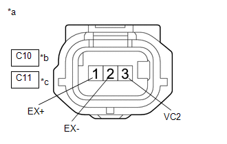
| *a | Front view of wire harness connector (to VVT Sensor (for Exhaust Camshaft)) |
| *b | Bank 1 |
| *c | Bank 2 |
HINT:
Make sure that the connector is properly connected. If it is not, securely connect it and check for DTCs again.
(a) Disconnect the VVT sensor (for exhaust camshaft) connector.
(b) Turn the engine switch on (IG).
(c) Measure the voltage according to the value(s) in the table below.
Standard Voltage:
| Tester Connection | Condition | Specified Condition |
|---|---|---|
| C10-3 (VC2) - Body ground | Engine switch on (IG) | 4.5 to 5.5 V |
| C11-3 (VC2) - Body ground | Engine switch on (IG) | 4.5 to 5.5 V |
| C10-1 (EX+) - Body ground | Engine switch on (IG) | 3.0 to 5.0 V |
| C11-1 (EX+) - Body ground | Engine switch on (IG) | 3.0 to 5.0 V |
(d) Turn the engine switch off and wait for at least 30 seconds.
(e) Measure the resistance according to the value(s) in the table below.
Standard Resistance:
| Tester Connection | Condition | Specified Condition |
|---|---|---|
| C10-3 (VC2) - C10-1 (EX+) | Engine switch off | 1.425 to 1.575 kΩ |
| C11-3 (VC2) - C11-1 (EX+) | Engine switch off | 1.425 to 1.575 kΩ |
| C10-2 (EX-) - Body ground | Always | Below 1 Ω |
| C11-2 (EX-) - Body ground | Always | Below 1 Ω |
| NG | .gif) | GO TO STEP 4 |
|
.gif)
| 2. | CHECK SENSOR INSTALLATION AND CONDUCT VISUAL INSPECTION (VVT SENSOR (FOR EXHAUST CAMSHAFT)) |
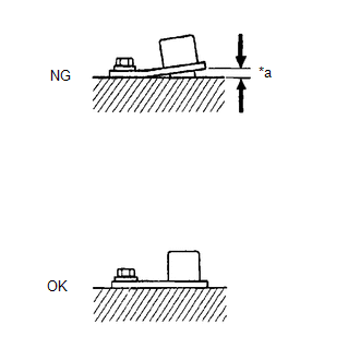
| *a | Clearance |
(a) Visually check the VVT sensor (for exhaust camshaft) for damage.
(b) Check the VVT sensor (for exhaust camshaft) installation condition.
OK:
The VVT sensor (for exhaust camshaft) does not have any damage and is installed properly.
| NG | | SECURELY REINSTALL VVT SENSOR (FOR EXHAUST CAMSHAFT) |
|
| 3. | INSPECT EXHAUST CAMSHAFT (TIMING ROTOR) |
(a) Check the timing rotor of the exhaust camshaft.
OK:
Camshaft timing rotor does not have any cracks or deformation.
HINT:
Perform "Inspection After Repair" after replacing the exhaust camshaft.
Click here
| OK | | REPLACE VVT SENSOR (FOR EXHAUST CAMSHAFT) |
| NG | | REPLACE EXHAUST CAMSHAFT |
| 4. | CHECK HARNESS AND CONNECTOR (VVT SENSOR (FOR EXHAUST CAMSHAFT) - ECM) |
(a) Disconnect the VVT sensor (for exhaust camshaft) connector.
(b) Disconnect the ECM connector.
(c) Measure the resistance according to the value(s) in the table below.
Standard Resistance:
| Tester Connection | Condition | Specified Condition |
|---|---|---|
| C10-1 (EX+) - C32-131 (EV1+) | Always | Below 1 Ω |
| C10-2 (EX-) - C32-100 (VV1-) | Always | Below 1 Ω |
| C10-3 (VC2) - C32-99 (VCV1) | Always | Below 1 Ω |
| C11-1 (EX+) - C32-130 (EV2+) | Always | Below 1 Ω |
| C11-2 (EX-) - C32-97 (VV2-) | Always | Below 1 Ω |
| C11-3 (VC2) - C32-98 (VCV2) | Always | Below 1 Ω |
| C10-1 (EX+) or C32-131 (EV1+) - Body ground and other terminals | Always | 10 kΩ or higher |
| C10-2 (EX-) or C32-100 (VV1-) - Body ground and other terminals | Always | 10 kΩ or higher |
| C10-3 (VC2) or C32-99 (VCV1) - Body ground and other terminals | Always | 10 kΩ or higher |
| C11-1 (EX+) or C32-130 (EV2+) - Body ground and other terminals | Always | 10 kΩ or higher |
| C11-2 (EX-) or C32-97 (VV2-) - Body ground and other terminals | Always | 10 kΩ or higher |
| C11-3 (VC2) or C32-98 (VCV2) - Body ground and other terminals | Always | 10 kΩ or higher |
| OK | | REPLACE ECM |
| NG | | REPAIR OR REPLACE HARNESS OR CONNECTOR |
READ NEXT:
 Catalyst System Efficiency Below Threshold Bank 1 (P042000,P043000)
MONITOR DESCRIPTION The ECM uses sensors mounted in front of and behind the Three-Way Catalytic Converter (TWC) to monitor its efficiency. The first sensor, the air fuel ratio sensor, sends pre-cataly
Evaporative Emission System Leak Detection Reference Orifice Low Flow (P043E00,P043F00,P24007E,P24007F,P24187E)
DTC SUMMARY DTC No. Detection Item DTC Detection Condition Trouble Area MIL Memory Note P043E00 Evaporative Emission System Leak Detection Reference Orifice Low Flow Reference o
Evaporative Emission System Incorrect Purge Flow Actuator Stuck On (P04417E,P04417F,P04419C)
DTC SUMMARY DTC No. Detection Item DTC Detection Condition Trouble Area MIL Memory Note P04417E Evaporative Emission System Incorrect Purge Flow Actuator Stuck On Leak detection
SEE MORE:
Camera Position Adjustment Incomplete (C1697)
DESCRIPTION This DTC is stored when the parking assist ECU judges that the camera initial setting has not been memorized (camera view adjustment is incomplete). DTC No. Detection Item DTC Detection Condition Trouble Area C1697 Camera Position Adjustment Incomplete Camera initial set
LTA (Lane Tracing Assist)
When driving on highways and
freeways with white (yellow) lane
lines, this function alerts the driver
when the vehicle might depart from
its lane or course* and provides
assistance by operating the steering
wheel to keep the vehicle in its
lane or course*. Furthermore, the
system provides st
