Lexus ES: "C" Camshaft Position Actuator Bank 1 Circuit Short to Ground (P136411,P136415)
DESCRIPTION
Refer to DTC P001001.
Click here .gif)
| DTC No. | Detection Item | DTC Detection Condition | Trouble Area | MIL | Memory | Note |
|---|---|---|---|---|---|---|
| P136411 | "C" Camshaft Position Actuator Bank 1 Circuit Short to Ground | While engine is running, short in VTM terminal of cam timing control motor with EDU assembly is detected for 3 seconds (1 trip detection logic). |
| Comes on | DTC stored | SAE Code: P1364 |
| P136415 | "C" Camshaft Position Actuator Bank 1 Circuit Short to Battery or Open | While engine is running, open or short in VTM and VTP terminals of cam timing control motor with EDU assembly is detected for 3 seconds (1 trip detection logic). |
| Comes on | DTC stored | SAE Code: P1364 |
MONITOR DESCRIPTION
These DTCs are stored when a power supply malfunction, diagnostic signal malfunction or motor operation signal malfunction is detected in the cam timing control motor with EDU assembly. The cam timing control motor with EDU assembly is equipped with a self diagnostic function, which is used to send diagnostic a signal (VTM) to the ECM. If the ECM receives a VTP or VTM open or short signal, a DTC is output immediately (1 trip detection logic).
MONITOR STRATEGY
| Related DTCs | P1364: Motor drive VVT system control module range check |
| Required sensors/Components (Main) | Cam timing control motor with EDU assembly |
| Required sensors/Components (Related) | - |
| Frequency of Operation | Continuous |
| Duration | 3 seconds |
| MIL Operation | Immediate |
| Sequence of Operation | None |
TYPICAL ENABLING CONDITIONS
| Monitor runs whenever the following DTCs are not stored | None |
| All of the following conditions are met | - |
| Auxiliary battery voltage | 11 V or higher |
| Power switch | On (IG) |
| Engine speed | 100 rpm or higher |
TYPICAL MALFUNCTION THRESHOLDS
Range Check (Low Voltage)| VVT driver communication terminal voltage level | Low |
| Either of the following conditions is met | A or B |
| A. VVT driver communication terminal voltage level | High |
| B. "VVT actuator circuit error" from motor drive VVT system control module | Received |
CONFIRMATION DRIVING PATTERN
HINT:
-
After repair has been completed, clear the DTC and then check that the vehicle has returned to normal by performing the following All Readiness check procedure.
Click here
-
When clearing the permanent DTCs, refer to the "CLEAR PERMANENT DTC" procedure.
Click here
- Connect the Techstream to the DLC3.
- Turn the power switch on (IG).
- Turn the Techstream on.
- Clear the DTCs (even if no DTCs are stored, perform the clear DTC procedure).
- Turn the power switch off and wait for at least 30 seconds.
- Turn the power switch on (IG).
- Turn the Techstream on.
-
Put the engine in Inspection Mode (Maintenance Mode).
Click here
- Start the engine [A].
- Idle the engine for 10 seconds or more [B].
- Enter the following menus: Powertrain / Engine / Trouble Codes [C].
-
Read the pending DTCs.
HINT:
- If a pending DTC is output, the system is malfunctioning.
- If a pending DTC is not output, perform the following procedure.
- Enter the following menus: Powertrain / Engine / Utility / All Readiness.
- Input the DTC: P136411 or P136415.
-
Check the DTC judgment result.
Techstream Display
Description
NORMAL
- DTC judgment completed
- System normal
ABNORMAL
- DTC judgment completed
- System abnormal
INCOMPLETE
- DTC judgment not completed
- Perform driving pattern after confirming DTC enabling conditions
HINT:
- If the judgment result is NORMAL, the system is normal.
- If the judgment result is ABNORMAL, the system has a malfunction.
- If the judgment result is INCOMPLETE, perform steps [B] through [C] again.
-
[A] to [C]: Normal judgment procedure.
The normal judgment procedure is used to complete DTC judgment and also used when clearing permanent DTCs.
- When clearing the permanent DTCs, do not disconnect the cable from the auxiliary battery terminal or attempt to clear the DTCs during this procedure, as doing so will clear the universal trip and normal judgment histories.
WIRING DIAGRAM
Refer to DTC P136001.
Click here
CAUTION / NOTICE / HINT
NOTICE:
- Inspect the fuses for circuits related to this system before performing the following procedure.
-
Vehicle Control History may be stored in the hybrid vehicle control ECU assembly if the engine is malfunctioning. Certain vehicle condition information is recorded when Vehicle Control History is stored. Reading the vehicle conditions recorded in both the Freeze Frame Data and Vehicle Control History can be useful for troubleshooting.
Click here
(Select Powertrain in Health Check and then check the time stamp data.)
Click here
-
If any "Engine Malfunction" Vehicle Control History item has been stored in the hybrid vehicle control ECU assembly, make sure to clear it. However, as all Vehicle Control History items are cleared simultaneously, if any Vehicle Control History items other than "Engine Malfunction" are stored, make sure to perform any troubleshooting for them before clearing Vehicle Control History.
Click here
HINT:
Read Freeze Frame Data using the Techstream. The ECM records vehicle and driving condition information as Freeze Frame Data the moment a DTC is stored. When troubleshooting, Freeze Frame Data can help determine if the vehicle was moving or stationary, if the engine was warmed up or not, if the air fuel ratio was lean or rich, and other data from the time the malfunction occurred.
PROCEDURE
| 1. | CHECK TERMINAL VOLTAGE (POWER SOURCE OF CAM TIMING CONTROL MOTOR WITH EDU ASSEMBLY) |
| (a) Disconnect the cam timing control motor with EDU assembly connector. |
|

(b) Turn the power switch on (IG).
(c) Measure the voltage according to the value(s) in the table below.
Standard Voltage:
| Tester Connection | Condition | Specified Condition |
|---|---|---|
| C54-2 (VB1) - Body ground | Power switch on (IG) | 11 to 14 V |
| NG | .gif) | GO TO STEP 8 |
|
.gif)
| 2. | CHECK HARNESS AND CONNECTOR (CAM TIMING CONTROL MOTOR WITH EDU ASSEMBLY - BODY GROUND) |
(a) Disconnect the cam timing control motor with EDU assembly connector.
(b) Measure the resistance according to the value(s) in the table below.
Standard Resistance:
| Tester Connection | Condition | Specified Condition |
|---|---|---|
| C54-3 (GND) - Body ground | Always | Below 1 Ω |
| NG | | REPAIR OR REPLACE HARNESS OR CONNECTOR |
|
| 3. | INSPECT CAM TIMING CONTROL MOTOR WITH EDU ASSEMBLY (BODY GROUND) |
.png)
(a) Check installation condition.
- Check that the 3 installation bolts of the cam timing control motor with EDU assembly are tightened to the specified torque.
Torque:
21 N*m (214 kgf*cm, 15 ft.*lbf)
| NG | | TIGHTEN TO SPECIFIED TORQUE |
|
| 4. | CHECK HARNESS AND CONNECTOR (CAM TIMING CONTROL MOTOR WITH EDU ASSEMBLY - ECM) |
(a) Disconnect the cam timing control motor with EDU assembly connector.
(b) Disconnect the ECM connector.
(c) Measure the resistance according to the value(s) in the table below.
Standard Resistance:
| Tester Connection | Condition | Specified Condition |
|---|---|---|
| C54-4 (VTM) - C88-72 (EMD1) | Always | Below 1 Ω |
| C54-1 (VTP) - C88-28 (EDT1) | Always | Below 1 Ω |
| C54-4 (VTM) or C88-72 (EMD1) - Body ground and other terminals | Always | 10 kΩ or higher |
| C54-1 (VTP) or C88-28 (EDT1) - Body ground and other terminals | Always | 10 kΩ or higher |
| NG | | REPAIR OR REPLACE HARNESS OR CONNECTOR |
|
| 5. | REPLACE CAM TIMING CONTROL MOTOR WITH EDU ASSEMBLY |
(a) Replace the cam timing control motor with EDU assembly.
Click here
HINT:
Perform "Inspection After Repair" after replacing the cam timing control motor with EDU assembly.
Click here
|
| 6. | CLEAR DTC |
(a) Connect the Techstream to the DLC3.
(b) Turn the power switch on (IG).
(c) Turn the Techstream on.
(d) Clear the DTCs.
Powertrain > Engine > Clear DTCs(e) Turn the power switch off and wait for at least 30 seconds.
|
| 7. | CONFIRM WHETHER MALFUNCTION HAS BEEN SUCCESSFULLY REPAIRED |
(a) Drive the vehicle in accordance with the driving pattern described in Confirmation Driving Pattern.
(b) Enter the following menus: Powertrain / Engine / Trouble Codes.
(c) Read the DTCs.
Powertrain > Engine > Trouble Codes| Result | Proceed to |
|---|---|
| DTCs are not output | A |
| DTC P136411 or P136415 is output | B |
| A | | END |
| B | | REPLACE ECM |
| 8. | INSPECT VVT RELAY |
(a) Inspect the VVT relay.
Click here
| NG | | REPLACE VVT RELAY |
|
| 9. | CHECK HARNESS AND CONNECTOR (VVT RELAY - CAM TIMING CONTROL MOTOR WITH EDU ASSEMBLY) |
(a) Remove the VVT relay from No. 1 engine room relay block and No. 1 junction block assembly.
(b) Disconnect the cam timing control motor with EDU assembly connector.
(c) Measure the resistance according to the value(s) in the table below.
Standard Resistance:
| Tester Connection | Condition | Specified Condition |
|---|---|---|
| 5 (VVT relay) - C54-2 (VB1) | Always | Below 1 Ω |
| 5 (VVT relay) or C54-2 (VB1) - Body ground and other terminals | Always | 10 kΩ or higher |
| NG | | REPAIR OR REPLACE HARNESS OR CONNECTOR |
|
| 10. | CHECK HARNESS AND CONNECTOR (POWER SOURCE OF VVT RELAY) |
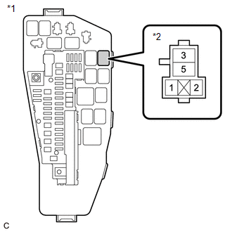
| *1 | No. 1 Engine Room Relay Block and No. 1 Junction Block Assembly |
| *2 | VVT Relay |
(a) Remove the VVT relay from No. 1 engine room relay block and No. 1 junction block assembly.
(b) Measure the voltage according to the value(s) in the table below.
Standard Voltage:
| Tester Connection | Condition | Specified Condition |
|---|---|---|
| 3 (VVT relay) - Body ground | Always | 11 to 14 V |
| NG | | REPAIR OR REPLACE HARNESS OR CONNECTOR (AUXILIARY BATTERY - VVT RELAY) |
|
| 11. | CHECK HARNESS AND CONNECTOR (POWER SOURCE OF VVT RELAY) |
| *1 | No. 1 Engine Room Relay Block and No. 1 Junction Block Assembly |
| *2 | VVT Relay |
(a) Remove the VVT relay from No. 1 engine room relay block and No. 1 junction block assembly.
(b) Turn the power switch on (IG).
(c) Measure the voltage according to the value(s) in the table below.
Standard Voltage:
| Tester Connection | Condition | Specified Condition |
|---|---|---|
| 1 (VVT relay) - Body ground | Power switch on (IG) | 11 to 14 V |
| OK | | REPAIR OR REPLACE HARNESS OR CONNECTOR (VVT RELAY - BODY GROUND) |
| NG | | REPAIR OR REPLACE HARNESS OR CONNECTOR (EFI-MAIN NO. 1 RELAY - VVT RELAY) |
READ NEXT:
 "E" Camshaft Position Actuator Bank 1 Signal Invalid (P136629)
DESCRIPTION Refer to DTC P001001. Click here DTC No. Detection Item DTC Detection Condition Trouble Area MIL Memory Note P136629 "E" Camshaft Position Actuator Bank 1 Signal Inv
Evaporative Emission Canister (Small Leak) (P142000,P142100)
DTC SUMMARY DTC No. Detection Item DTC Detection Condition Trouble Area MIL Memory Note P142000 Evaporative Emission Canister (Small Leak) Leak detection pump creates negative p
Evaporative Emission Fuel Tank (Small Leak) (P142200,P142300)
DTC SUMMARY DTC No. Detection Item DTC Detection Condition Trouble Area MIL Memory Note P142200 Evaporative Emission Fuel Tank (Small Leak) Leak detection pump creates negative
SEE MORE:
Components
COMPONENTS ILLUSTRATION *1 COOL AIR INTAKE DUCT SEAL *2 FRONT FENDER SPLASH SHIELD SUB-ASSEMBLY *3 HOOD STAY BRACKET *4 HOOD SUPPORT ASSEMBLY *5 HOOD SUPPORT BRACKET *6 NO. 3 COWL TOP PANEL INSULATOR N*m (kgf*cm, ft.*lbf): Specified torque - -
Problem Symptoms Table
PROBLEM SYMPTOMS TABLE NOTICE:
If the battery voltage becomes low, battery load control will operate in order to ensure sufficient power is supplied to the power steering system. In this case, the windshield deicer system may not operate.
HINT:
Use the table below to help determine the caus
